Final Project: Digital Version Of Rock, Paper, Scissors
WHO: Our main audience was young adults that were interested in enrolling in engineering classes. Mainly those dealing with digital electronics.
WHAT: We chose to build a digital version of the well-known game Rock, Paper, Scissors using simple AOI logic, Synchronous Counters, Seven Segment Displays and LED's.
WHY: This project demonstrates how one could apply concepts learned in an engineering class to something creative and fun. Because the process wasn't too complex, it will be easier to explain to those who are interested in the field. This way we don't scare them off with something that is way over their head.
HOW: We built this game going through a set of simple steps.
1. Brainstorm/Sketch a Design
2. Figure out the logic needed, and create a Truth Table
3. Use the Truth Table to K-Map
4. Identify Minterms
5. Use a Circuit Design Software to create a simulation of the circuit
6. Build a physical circuit on a Digital Logic Board.
Brainstorming:
Sketch/Rough Draf
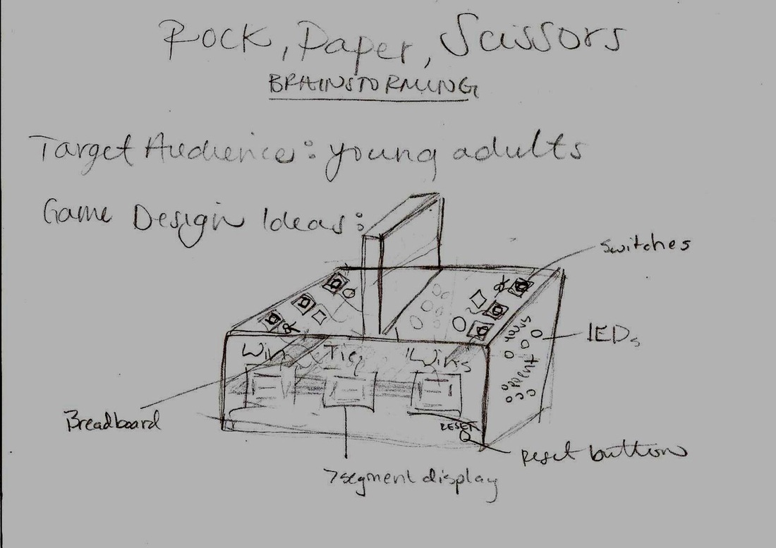
To start off, we had to think of how the game itself would look. With a given restraint of the actual circuitry having to be enclosed in a box, we started from there. The game set up is similar to that of Battleship. Each player is set up on the opposite side of the box with a barrier in between. The barrier is to prevent any wandering eyes from cheating. Three buttons are on each side of the board, each designated for either rock, paper, or scissors. On the side of the box there are two seven-segment displays used to show the score. And inside the box will be all the confusing wires, breadboards, and gates. Above each button for the choice selection is a LED that will light up when you have chosen that option. Maurice Karnaugh
The man responsible for creating the wonderful method.
|
Finding the Minterms
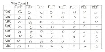
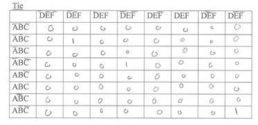
To be able to begin designing the circuit of our game, we had to find out all possible combinations, which ones would work, which ones wouldn't. We did this by creating a Truth Table. (Shown Below). In the truth table all of the options highlighted in red cannot happen because that would indicate that more than one button is pressed (aka someone is cheating). The ones highlighted in green are the options in which a win or a tie would occur, and white is when only one opponent has made a selection. 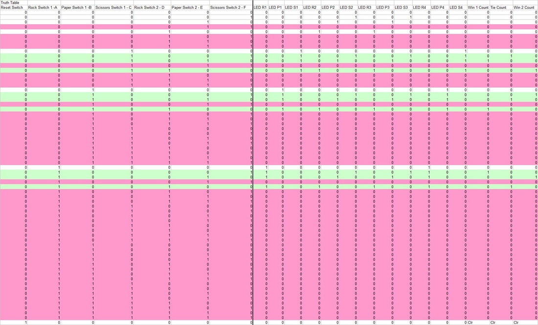
K-MappingThe Truth Table gave us a few Unsimplified minterms these are shown below.
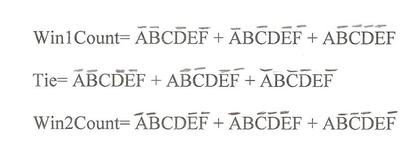
Using Karnaugh Maps (K-Maps, which is a pictorial method used to minimize Boolean expressions without having to use Boolean algebra theorems or equations) we tried to decrease the size of these equations.
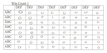
In the end the K-Mapping was ineffective and the minterms stayed the same length.
|
Designing the Circuit.

Thanks to my other three group members, i was able to overcome the struggle of designing the circuit. I honestly could not have done it without them, and i give them the majority of credit for this portion of the project. I did my best to contribute the knowledge i had of circuitry design but they are quite savy with this sort of thing.
ANYWAYS... we took what we had learned in previous lessons, and modified it slightly to do what we needed it to do in our game. We were going to have to use NOR gates, NAND gate, OR gates, AND gates, 193 MSI Counters, Seven Segment Display's,seven segment display encoders, 220 ohm resistors, and D-flip flops (which were later on replaced with SR latches).
ANYWAYS... we took what we had learned in previous lessons, and modified it slightly to do what we needed it to do in our game. We were going to have to use NOR gates, NAND gate, OR gates, AND gates, 193 MSI Counters, Seven Segment Display's,seven segment display encoders, 220 ohm resistors, and D-flip flops (which were later on replaced with SR latches).
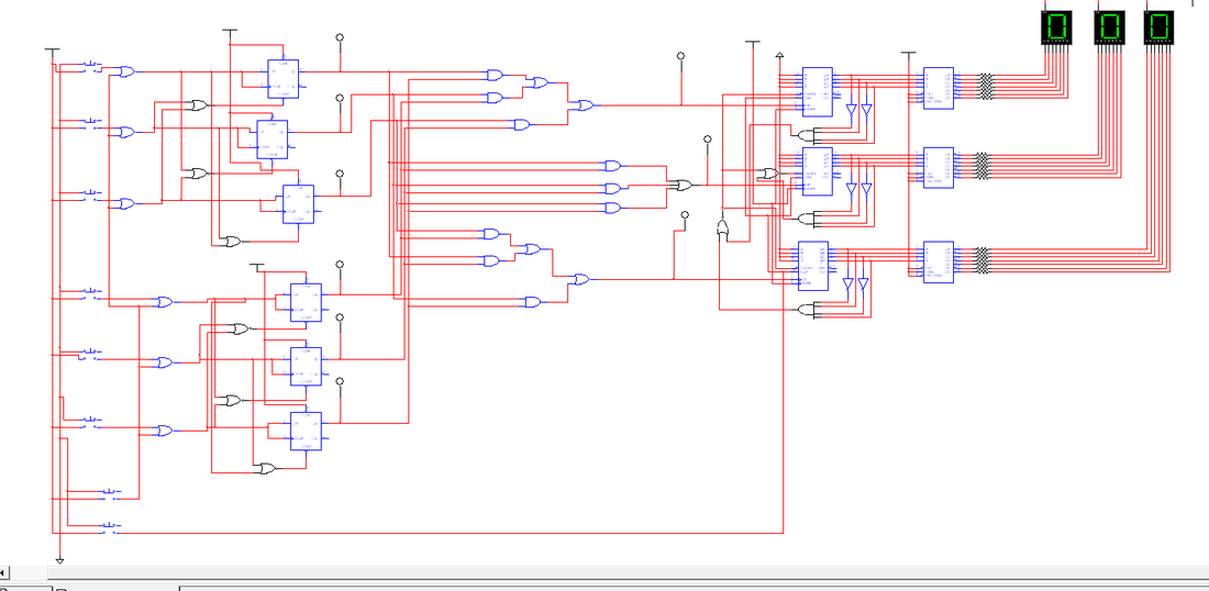
-The first part of the circuit with the Nor gates, D-Flip flops, and OR gates is to prevent a player from pressing more than one button at a time. (This would help them win almost every time). Then Q, on the D-Flip that is connect to the button you chose will output a 1, there for lighting up the LED to help indicate which option you have chosen. (this part of the circuit is later on replaced). - The second half of the circuit (on the right hand side), the option that is chosen outputs a logic 1 and goes through a series of AOI logic, then from here it goes into either a 3 in put Or gate. From here it goes into a MSI synchronous counter to keep count of the number of wins and ties. Then finally the outputs are sent through a Seven Segment Display Encoder then through resistors and into the Seven Segment display. |
This video is proof of the circuit working in MUlti-Sim. Using buttons on the keyboard, a few games of rock, paper scissors were played, and the ties, and wins were counting correctly.
|
The Physical Prototype
Below is the first breadboard, the one responsible for the selection, and the reset line. We first used D-Flip Flops to prevent more than one selection. For some reason it wasn't working. We found that a few were not plugged into power and ground, so after fixing that we hoped that it would work.. But unfortunately that wasn't the case. SO we pulled out the majority of the wires you see below and replaced them with an SR latch. This can be seen in the second slide show.
The third slideshow is the second half of the circuit. It is responsible for counting. it takes the outputs from the first breadboard, and feeds them thorugh AOI logic into an MSI synchronous counter (74LS193). Then from there into a seven segment display encoder then to the displays themself.
The third slideshow is the second half of the circuit. It is responsible for counting. it takes the outputs from the first breadboard, and feeds them thorugh AOI logic into an MSI synchronous counter (74LS193). Then from there into a seven segment display encoder then to the displays themself.
Breadboard #1
The SR LATCH
Bread Board #2
The Final Product
Once contained inside a box, the circuit is less intimidating. If the physical protype actually worked, this game would've been way cool. With a little bit more time i think that it would be possible. With such a large circuit, so many small things can go wrong. You get problems like D-Bounces, and voltage drops. We were constantly changing batteries and running into one problem after another. Some of these problems being a simple wiring mistake and some being a complex problem that i was clueless about.
