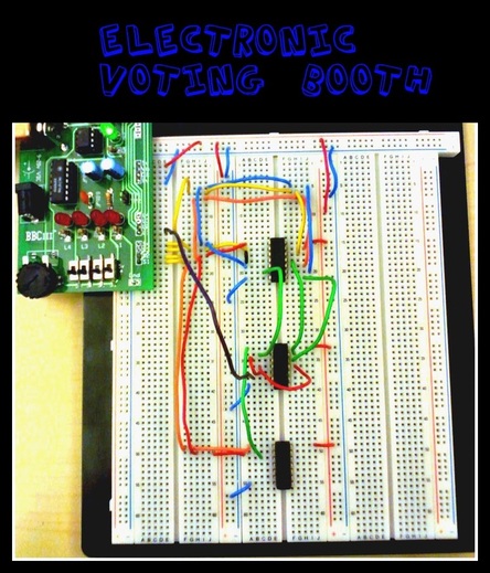
Problems/Constraints:We were asked to construct an electric voting machine that would allow four members to cast their ballots and display the past/fail status of their decision. An electric voting booth is needed because paper ballots were thought to be unreliable. The voting members are the President, the Vice President, the Secretary, and the Treasurer. If there was a tie, one of the members has to take priority, in this case the President takes priority. For example if the President and Vice President vote yes, but the secretary and treasurer vote no the proposition would pass as yes because the president takes priority. To implement this, we had to use AOI Logic. AOI stands for AND, OR and Inverter, this is referring to the types of gates. A Gate is used to connect minterms (possible combinations) in a certain way. When you AND two options together it simply mean this AND that will give you a correct output. When you OR something together, it means the OR that, meaning that if you get this answer or that answer you will get the correct output. Lastly and inverter simply turns a yes into a no, in makes the input opposite.
Brainstorming:To start out, one would have to find out all the combinations of votes the would pass the proposition or decline it in other words one has to determine the minterms. To do this you must create a Truth Table (a table that displays different inputs and their outputs) this shows which inputs make the final decision a yes or a no. This Truth Table is located second from the top on the right. From this you can write out the Unsimplified Logic Expression, which is all of the different combinations that would allow the output to be a 1(yes). Decision = P'VST + PV'S'T + PV'ST + PVS'T' + PVS'T + PVST' +PVST (if a letter has an " ' " after it, that means it is the Not version of the letter)
|

Truth Table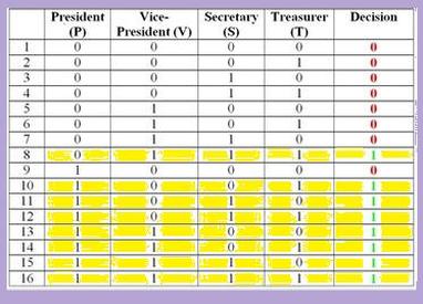
|
|
From this you can create a drawn up a version of the circuit. This would be the Unsimplified version, later on you learn how to make the equation much smaller. To draw up the circuit, you must connect each letter (the regular one or the inverted one) to the gate that is needed. For example if you had to wire up P' and V so that they are P'V, you must take each of them and wire them into an AND gate. In an AND gate there are multiple places to place to wires. Starting from the top left following the rows down, it goes input, input, then output. In the following picture it shows an example of an AND gate. The red squares are where the inputs go and the orange are where the outputs are. Each of these chips have to be powered, the green square is where the gate will be hooked up to power and the blue is where the gate will be hooked up to ground. The purple half circles in the center represent a AND gate. Those are what you will see in the drawing. OR gates works the same exact way except when you OR the two in puts together, for example A or B, instead of AB it makes the output A + B ( + the plus sign mean's or ). OR gates are represented by an almost crescent moon shape. Inverters are slightly different, it's simply one input then one out put, so instead of red red yellow, it is red yellow red yellow... and so on. Inverters are represented by a triangle with a small circle at the point.
|
NAND Gate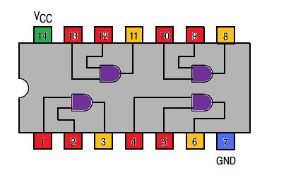
Unsimplified Sketch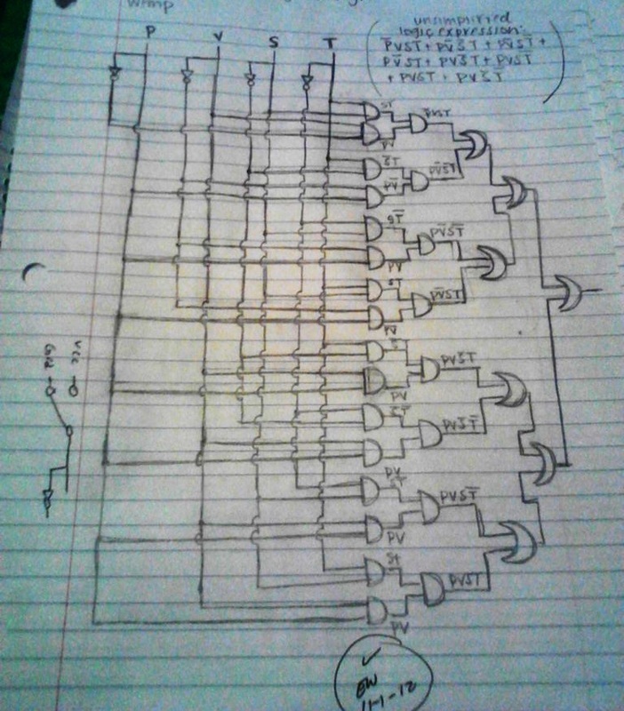
|
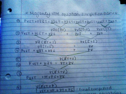
Calculations
Now, to eliminate work that doesn't need to be done, you must use Boolean Algebra to simplify the equation you received from the truth table. Boolean Algebra is a collection of Theorems and Laws that allow one to simplify an equation such as this. Below is a step by step simplification process i went through to simplify the Voting Booth equation.
|
Now that the equation is simplified, i simpler circuit may be drawn up, still using AND and NOR gates, but now there is less out puts. The final equation being VST+VP+PT+PS, the actual wiring of the circu
|
Simplified Circuit Design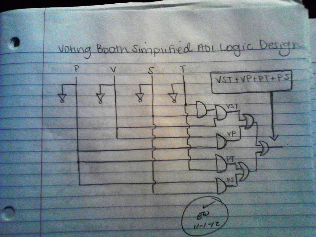
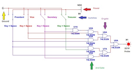
Simplified Circuit MultiSim |
Final ProductNow that there is a simplified circuit, it can be built and test in a circuit design software, where a simulation can take place. This is done in MultiSim, where skills of their own are required. When finished the MultiSim product looks like the picture to the right.
The Red circle at the right of the picture is a probe, this is used to test the circuit. To do this you must flip the switches, which are pointed at by the blue arrow. They represent the vote of each the Treasurer, Secretary, Vice President and the President. When switched to the straight position they are on and when they are not they are off, which means the vote is a no. The green arrow is pointing to the AND gates that were previously discussed. The Purple is pointing to an OR gate. The Red arrow is pointing towards the power supply or VCC, which is at 5 volts for this circuit. The yellow is referring to the ground which is required for the circuit to work. |
|
Final Circuit Breadboard Implementation
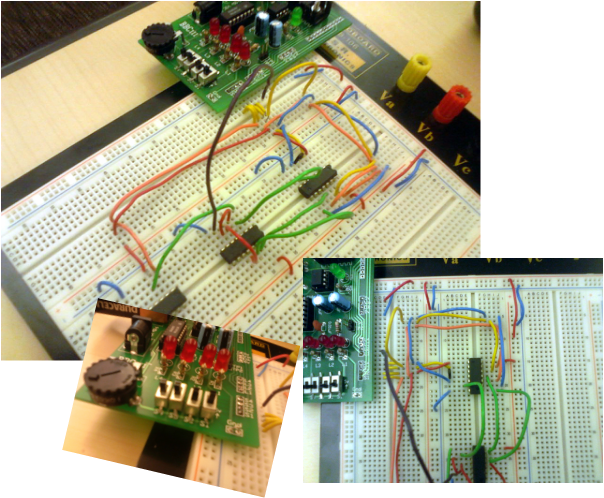
To Breadboard a product is to simply take the circuit you previously drew and built in MultiSim and build a real life version. The black squares are the AND, OR and Inverter gates. In that order as well. Each input is coming from a switch and into a gate to be either AND or OR'd together. Just like the drawings. Then the final output is wired to a red light, as you can clearly see in the bottom left picture. If the correct switches are flipped the light will come on.
Reflection
The project has been explained in the previous headings. But there are a few things you can run into when building a circuit. It seems no better what there is always going to be trouble shooting. There is a variety of reasons as to why this may happen. A wire might not be fully plugged in, the battery may be dead, and so on. It is a pain, but the results or worth it. I think i had a fairly easy time building this circuit, if i would go back and redo it i would shorten up the wires so the appearance is neater.
